Academic Project
CanTreelever
Timber Battens and 3D-Printed Nodes
- Year
- June 2023
- Classification
- Academic Project
- Status
- Course project, 4480 Contemporary Building and Structural Systems
- Location
- Izmir, Türkiye
- Designer
- Gökalp Kalfa & Zehra Çelik
- Team
- Gökalp Kalfa
- Zehra Çelik (opens in a new tab)
- Emirhan Duğral
- Ece Hepmutlu
- Elif Kır
- Berkin Değirmenci
- Zeynep Diker
- Bengisu Şengün
- Murat Şen
- Ecenaz Adıgüzel
- Işıl Sezer
- Consultants
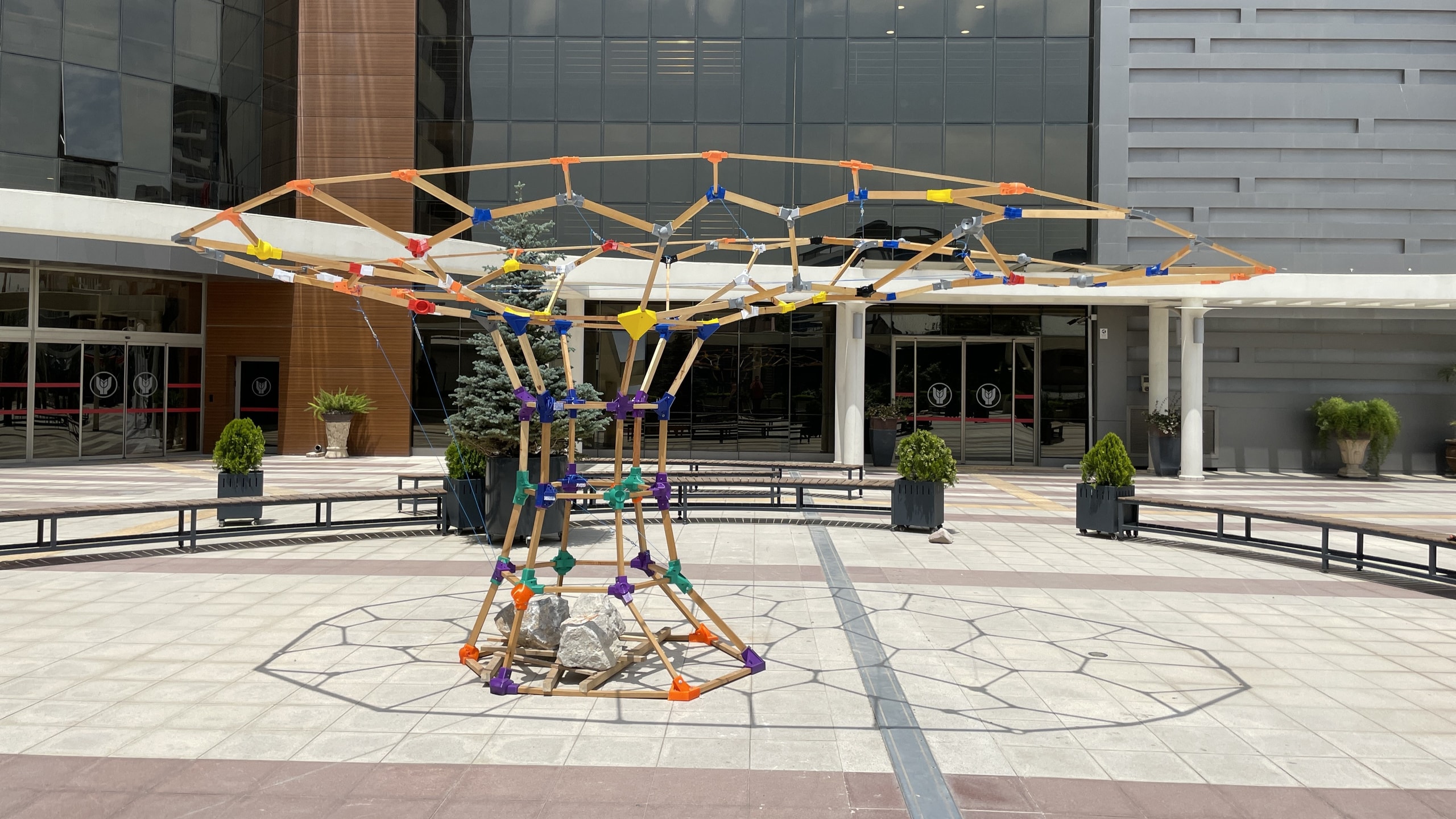
Our aim in this project was to design, fabricate and assemble a free-form gridshell within a single twelve-week course. The structure combines timber battens with 3D-printed connections, a hybrid technique that makes free-form structures possible with standard building materials and ordinary 3D printers. It also had to be designed for disassembly.
Students first explored the design through digital and physical form-finding, then each presented a proposal. The project to be built was chosen by a vote among the students and developed further by the whole class. Structural and fabrication limits, including a cap of 110 nodes, shaped the final canopy.
Nodes and Fabrication
The students then designed the 103 connection nodes, weighing 3D-printing parameters such as filament (PLA+), print time, infill and orientation. The aim was to make the nodes as strong as possible and easy to assemble with the timber pieces, so some were designed as a single piece and others in two pieces, with holes for screws and cables.
The printing followed the assembly sequence. The column, the supporting part, was built first. Once it was ready, the nodes for the canopy were designed and printed; with the canopy's smaller bar sections, these printed faster. The last nodes to be designed and printed were those joining the canopy to the column, which were also the last to be assembled. The timber battens were cut, the column and the canopy were built separately, and the two were joined in the final stage.
Learning from Failure
Shortly after it was installed outdoors, the structure was brought down by a strong wind. The evaluation that followed found that one of the column nodes had been overstressed and broke, causing the whole structure to lose stability. The column nodes were redesigned for greater strength and printed in PETG, and cables were added for stability. The second version performed very well in strength and stability, but high summer temperatures made the nodes soften and melt, leading to large deflections of the canopy.
The final prototype is a proof of concept for hybrid fabrication as a way to build temporary structures in architectural education. The process of design, production, assembly and disassembly, and its failures, was later published in Learning from Failure.